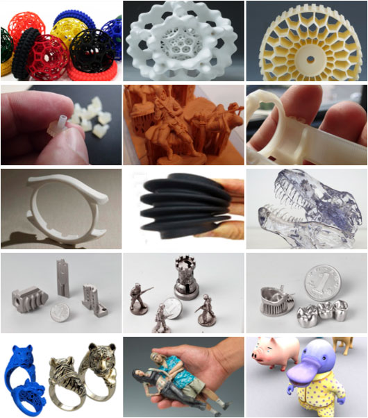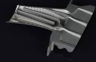
Guide
- How to Calculate 3D Printing Price (SLS, SLA, SLM, MJF, FDM, ETC.,)
- Anodizing vs. Painting: An In-depth Analysis
- 9 Types of 3D Printed Metal Copper Techniques
- 3D Printing Materials and How to Choose the Right One?
- What Is Micro Manufacturing Technology
- Wire 3D Printing: Process, Filament, Printer and Features
- Uncover The Mystery Of CNC Machining
- Huazhong University of Science and Technology has made new breakthroughs in ultrafast laser 3D printing of fine and complex semiconductor micro-nano structures
- In 2025, there will be more than 600 metal 3D printing equipment serving China’s aerospace and other fields
- Looking at the development trend of 3D printing from Formnext 2021
- 3D printed prototype silica gel molds, realizing small batch production of industrial products
- Global architectural 3D printing inventory, no need to move bricks to build a house
- The latest application cases of 3D printing in aviation
- 3D printing everything? Japanese media: Printable buildings, parts, organs and even food…
- 3D printing provides emergency production of anti-epidemic products, global anti-epidemic
Case Studies

Stereolithography 3D Printing
3d-printing-china.com has all kinds of SLA equipment and all kinds of materials
What Is SLA 3D Printing?
Stereolithography Technology (SLA) is a rapid prototyping technology that first appeared and realized commercialization in the world, and it is also one of the most in-depth and widely used rapid prototyping technologies. It mainly uses photosensitive resin as a raw material, and utilizes the characteristic that liquid photosensitive resin will cure quickly under ultraviolet laser beam irradiation. The photosensitive resin is generally liquid, and it immediately initiates a polymerization reaction and completes curing when irradiated with a certain wavelength of ultraviolet light (250 nm to 400 nm). SLA focuses on the surface of the light-curing material by focusing ultraviolet light of a specific wavelength and intensity to solidify it sequentially from point to line and from line to surface, thereby completing the drawing of a layered cross-section.
SLA is one of the three main technologies used in 3D printing, as well as Fused Deposition Modeling (FDM) and Selective Laser Sintering (SLS). It belongs to the category of photosensitive resin 3D printers. A similar technology usually combined with SLA is called digital light processing (DLP). It represents an evolution of the SLA process, using a projector screen instead of a laser.
Although not as popular as FDM technology, SLA is actually the oldest additive manufacturing technology. The term “stereolithography” is derived from ancient Greek. “Three-dimensional” and “(photo) lithography” mean “solid” and “light writing form” respectively.
As the oldest additive manufacturing technology, SLA is sometimes considered the “mother of all 3D printing technologies.” It was developed by the American company 3D Systems, which was founded by Chuck Hull in 1986. Hull coined the term “stereolithography” in 1986. He defined this technology as a method of making 3D objects by continuously printing thin layers of ultraviolet curing. Light.
In 1992, 3D Systems created the world’s first SLA device, which can manufacture complex parts layer by layer in a small amount of time. SLA was the first to enter the field of rapid prototyping in the 1980s and continues to develop into a widely used technology.
As in the case of many additive manufacturing processes, the first step involves designing a 3D model through CAD software. The generated CAD file is a digital representation of the desired object.
If they are not automatically generated, the CAD files must be converted to STL files. Standard Tessellation Language (STL) or “Standard Triangle Language” is the native file format of stereolithography software created by Abert Consulting Group in 1987 for 3D Systems. STL files describe the surface geometry of 3D objects, ignoring other Common CAD model attributes, such as color and texture.
The pre-printer step is to feed the STL file to 3D slicer software, such as Cura. These platforms are responsible for generating G-code, which is the native language of 3D printers.
SLA-level equipment has a pivotal role in the face of model proofing, industrial design, and the medical industry. The advantages of high-precision molding technology and rapid prototyping determine its ability to help advance in this type of industry.
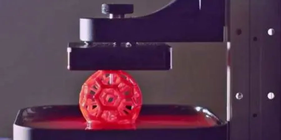
When the process begins, the laser “pulls” the first layer of printed matter into the photosensitive resin. No matter where the laser hits, the liquid will solidify. A computer-controlled mirror guides the laser to the appropriate coordinates.
At this point, it is worth mentioning that most desktop SLA printers are upside down. In other words, the laser points to the build platform, which starts from a low position and gradually rises.
After the first layer, the platform is raised according to the layer thickness (usually about 0.1 mm) and the additional resin is allowed to flow under the already printed part. The laser then cures the next cross section and repeats the process until the entire part is complete. The resin that has not been contacted by the laser remains in the barrel and can be reused.
After the material is polymerized, the platform is raised from the tank and the excess resin is discharged. At the end of the process, the model is removed from the platform, the excess resin is washed, and then placed in a UV oven for final curing. Post-press curing allows the object to reach the highest possible strength and become more stable.
Table of Contents
Why Choose 3d-printing-china.com SLA 3D Printing Service
PTJ meets or exceeds the quality standards of the world’s most demanding industries with our state of the art equipment and quality standards. Our precision and productivity is made possible by our ultimate success factor: the presence of skillful, knowledgeable PTJ experts in sla 3d printing and more additive manufacturing parts.
- No minimum order quantity
- Metal or plastic 3D printed prototype and production parts in 7-10 days
- Precision custom 3D printing parts at affordable prices
- Online free quote in the shortest time
- Single prototypes or complex shapes are both allowed
- A wide selection of metal or plastic materials
- Commercial and industrial-grade 3D printers
- Cooperative supplier assistance project
- Provide a quick solution for small batches of complex prototypes
- Provide a quick solution for small batches of complex prototypes
- We provide with our partner
- 3D printing services for metals and plastics
- Meet the rapid needs of complex prototype designers
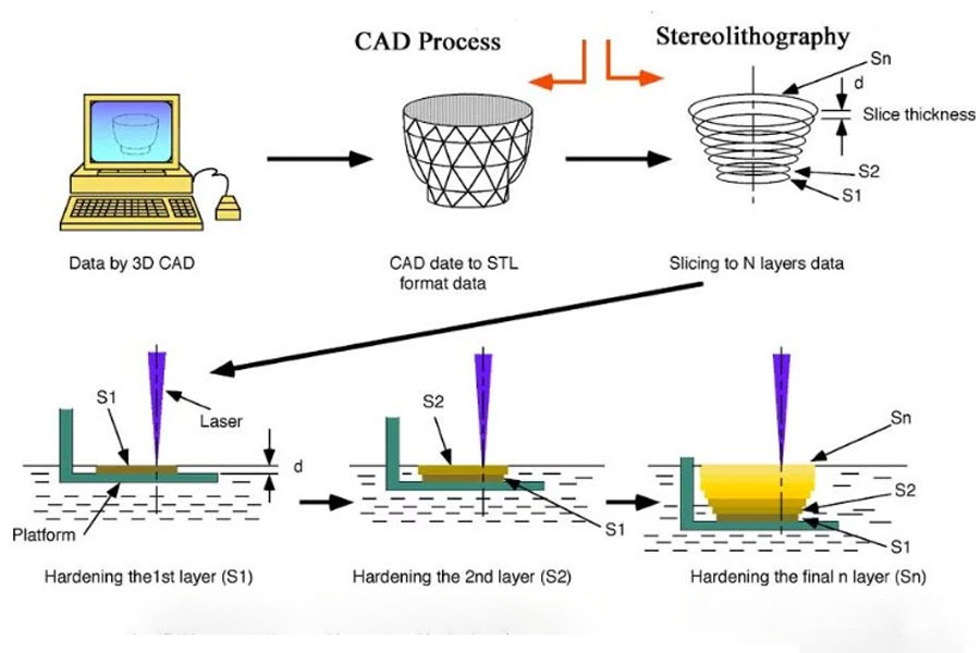
SLA 3D Printing Process
- Control the printing screen to sink to a certain height below the resin surface, so that the screen is covered with a layer of material.
- The computer controls the laser and galvanometer, and uses UV laser to scan the cross-section of the part currently to be printed, and solidify the part of the material that needs to be printed from liquid to solid.
- After the scanning is completed, the screen sinks to a certain height, and the squeegee spreads a layer of material (the main function is to smooth and fill the large flat material), and repeat the above step 2 until the printing is completed.
- After the printing is completed, take out the printed product, which needs to be cleaned with absolute ethanol and second-cured by ultraviolet light.
The Characteristics of SLA 3D Printing
The printing material of SLA is a liquid resin. During the curing process, the monomer carbon chains that make up the liquid resin will be activated by the UV laser and become solid, thereby forming a strong and indestructible bond between each other. The photopolymerization process is irreversible, so SLA parts cannot be converted back to a liquid state, and they will burn rather than melt when heated.
The height of the printing layer in the SLA process is between 25 and 100 microns. Lower layer heights can more accurately capture curved geometries, but will increase build time (and cost) and the possibility of printing failures. A layer height of 100 microns is suitable for most common applications.
The construction area is another parameter that is very important to the designer. The build size depends on the type of SLA machine. 3d-printing-china.com 3D’s supply chain system has almost all types of SLA equipment on the market, with full coverage of construction area (printing size) and printing materials.
The Support Structure of SLA
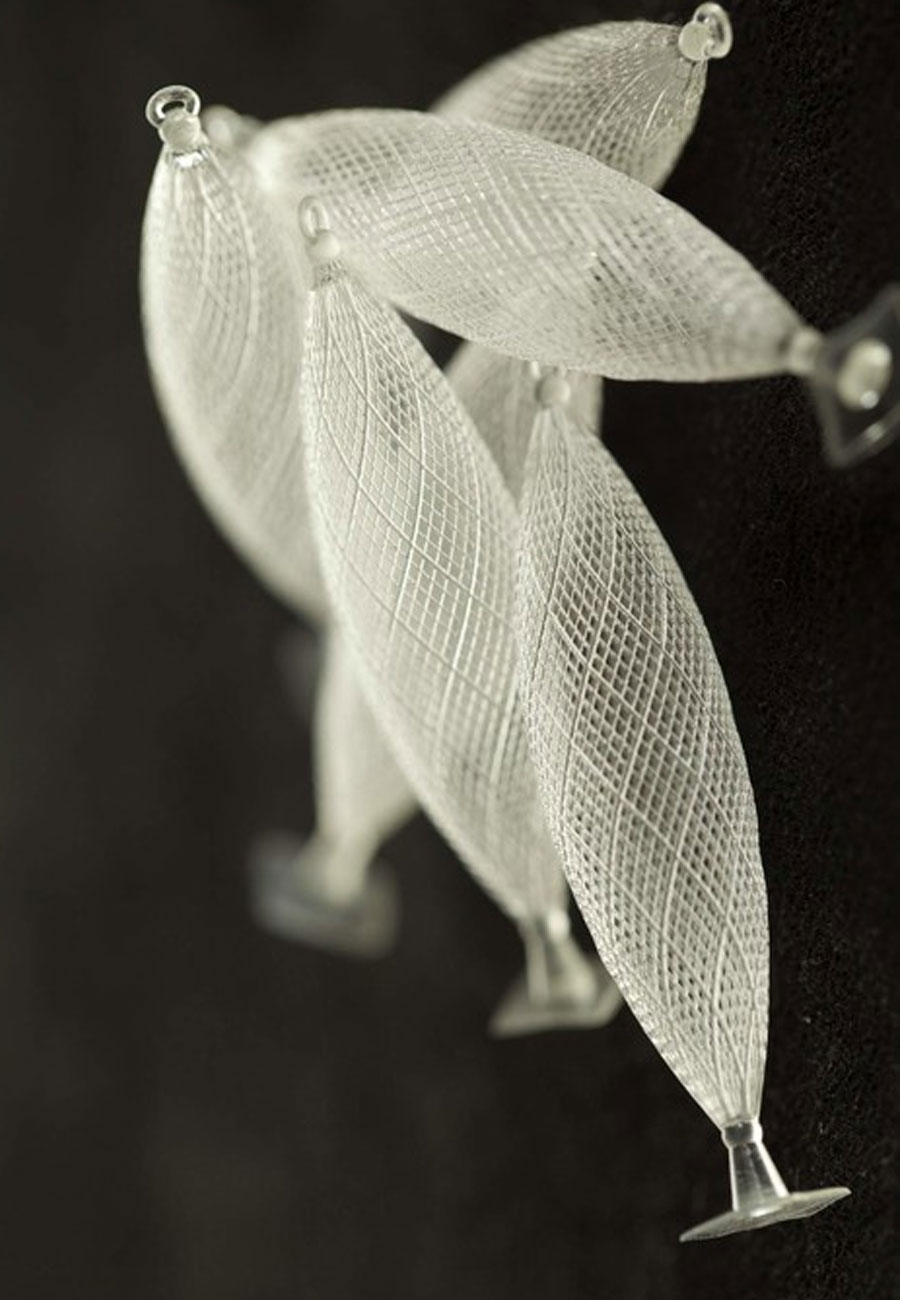
SLA’s 3d printing process principle determines that a supporting structure must be required during the printing process. The support structure is printed with the same material as the part and needs to be removed manually after printing. The direction in which the part is printed determines the position and number of supports. The print placement is to properly orient the parts so that the visual critical surface does not contact the supporting structure.
The bottom-up and top-down SLA printer usage support methods are different:
- In top-down SLA printers, supports are required to accurately print overhangs and bridges (the critical overhang angle is usually 30 degrees). Parts can be oriented in any position, but different orientation methods will result in different printing time and product quality. They are usually printed in a flat shape to minimize the amount of support and the total number of layers.
- In bottom-up SLA printers, the situation is more complicated. Overhangs and bridges still need to be supported, but minimizing the cross-sectional area of each layer is the most critical consideration. The force applied to the part during the peeling step may cause the part to detach from the build platform. These forces are proportional to the cross-sectional area of each layer. Therefore, the parts are oriented at a certain angle and reducing support becomes a major problem.
The Application Of SLA 3D Printing
- Quickly process high-precision, high-surface quality, multi-detail prototypes, which can be used in automotive molds, medical biology, consumer electronics, game animation, architectural design, sculpture modeling, home decoration and other fields. Concept models, general components, appearance verification , Assembly check, in some cases can be used for functional testing.
- There are corresponding characteristic materials for special requirements, such as heat-resistant resin and fully transparent resin.
The Design Principles of SLA 3D Printing
For thicker models, if shelling does not affect its performance, it is recommended to shell out, which can reduce the weight of the model and reduce the cost of the model. For large-surface models, it is recommended to add stiffeners after shelling, which can greatly reduce the degree of deformation of the model. Of course, this should be based on the specific analysis of the structure of the model. The minimum wall thickness requirement of the SLA process is related to the overall size. As the product size increases, the wall thickness should be increased accordingly. For small size parts (≤200mm) and medium size parts (200-400mm), the recommended minimum wall thickness is 2mm. For large size parts (≥400), the minimum wall thickness is recommended to be greater than 3mm.
As mentioned earlier, the SLA process needs to add support to the cantilever. The critical value of the cantilever angle is generally 35°. Therefore, the angle between the cantilever and the bottom surface can be designed to be greater than 35 when the model is designed without affecting the performance of the model. °, adding rounded corners when appropriate can reduce the support and ensure the model size and surface quality.
For concave text or surface details, it is generally recommended that the line width is at least 0.35mm and the depth is 0.35 mm. For raised text or surface details, it is recommended that the width be at least 0.35mm and the protrusion height should be at least 0.35 mm.
The assembly model generally has multiple independent shells. For the assembly that is easy to disassemble, we choose to disassemble and print, so that it will not affect the free placement of various parts and the best surface quality of the product. It is generally recommended to assemble The gap> 0.3mm.
But for some movable models that are printed in one piece, some parts cannot be disassembled, of course, they can also be printed. Generally, it is recommended that the assembly gap is ≥0.4mm, otherwise it may be printed as one with other parts.
Sometimes for printing convenience, you can also use support beams to connect all the shells, so that you can ensure that your parts will not be lost during mass printing. Generally, it is recommended that the thickness of the support beam is not less than 3mm.
The placement of the model has a great influence on the surface quality and strength of the product. Generally, it is recommended that the complex features of the workpiece face up, and the step texture of the curved workpiece horizontally is very obvious. Similar to a contour map, it is generally recommended to be 45° with the bottom surface of the platform. Place it at an angle of ° or upright, the long workpiece and the scraper are generally placed vertically or at an angle of 45°.
For oversized pieces that exceed the size of the printing platform, splicing can be used, and the splicing gap is generally recommended to be greater than 0.3mm. When splicing, you can add triangles, rectangles, serrations, bosses and pin types for positioning and connection, and use AB glue for bonding.
In order to ensure the smooth flow of the liquid resin from the cavity of the model after the shell is extracted, to reduce the weight of the model and reduce the cost of model production, holes should be made on the non-important surface of the model. The aperture diameter is related to the size of the model’s open surface, but it is generally recommended The minimum aperture is 3mm and the maximum is 30mm. The specific design should be based on the size of the model and the specific structure. After the post-processing is completed, the process holes can be blocked, and the notches can be used for positioning, and then a proper amount of polishing is enough.
For simple coloring parts, you can use integrated printing and then coloring. For complex coloring parts, the coloring model should be disassembled according to the coloring requirements, and then assembled after coloring. The assembly principle is in accordance with the splicing principle. Leave connection structure and gaps.
- Minimum detail wall thickness: 0.6mm (large-area sheet thickness should be greater than 2mm);
- The smallest independent column diameter: 1mm;
- The smallest convex (concave) stroke width: 0.35;
- The smallest convex (concave) stroke width: 0.35;
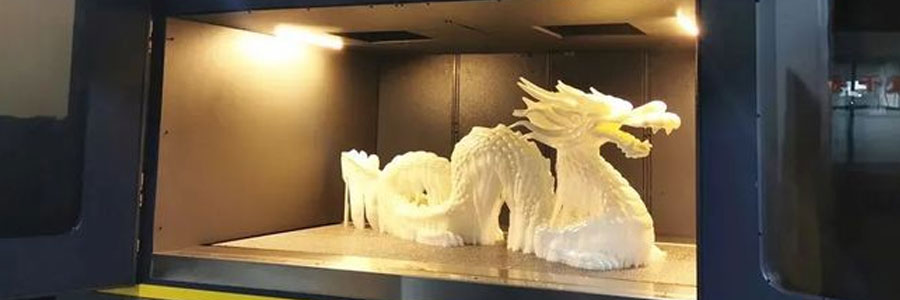
SLA 3D Printing vs LCD 3D Printing
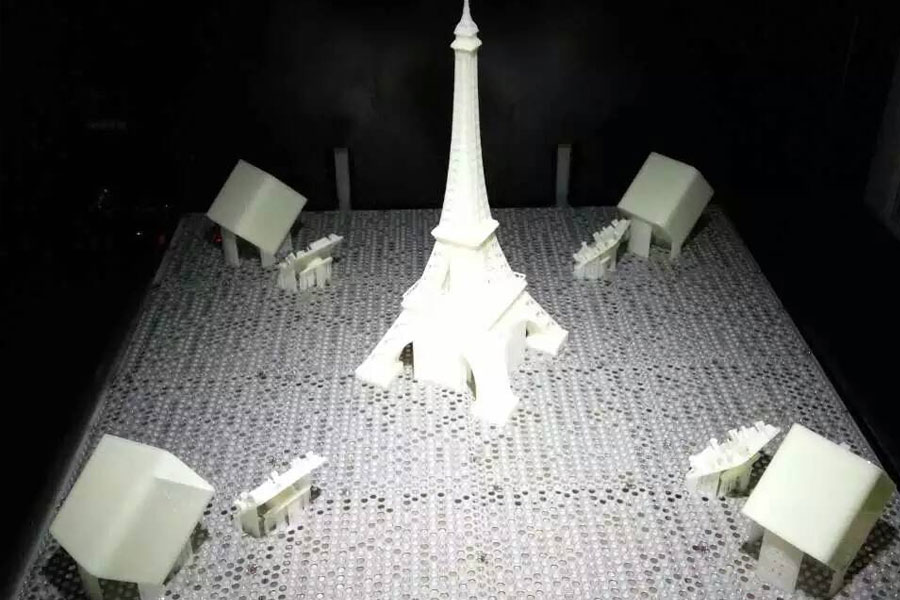
Each technology has its own advantages and limitations, but which technology is most suitable for you What about the job requirements? In 3D printing, whether it is metal printing, plastic printing, powder printing, all 3D printing technologies are based on a common principle, cutting the 3D model horizontally into separate cross-sections. We call this step slicing. Then print on the platform one by one upwards, and finally form a three-dimensional object. However, the three technologies of SLA and LCD use different molding techniques to print these cross-sectional layers.
Desktop-level SLA printing technology is the same. It uses resin consumables. Unlike LCD, the curing light wavelength of his resin consumables. When facing different wavelengths of light, the corresponding wavelength resin consumables should be used to avoid affecting the printing quality. The SLA desktop-level molding method is very similar to LCD. It consists of three major parts: resin feeder, printing platform, and laser transmitter. When printing, pour resin consumables into the resin feeder, the platform is lowered into the feeder, and the laser transmitter According to the shape of the slice layer, the resin in the trough will be scanned and cured through a laser galvanometer, and it will rise layer by layer to obtain a fine three-dimensional model. Because the SLA molding process is a laser scanning curing process, the molding accuracy is very high and the speed is fast, and the laser scanning speed can reach 5M/S.
Advantages And Disadvantages Of SLA 3D Printing
- SLA parts are usually very brittle and not suitable for functional prototypes.
- When parts are exposed to sunlight, the mechanical properties and visual appearance of SLA parts will decrease over time. (For the above two shortcomings, in general, you can choose special materials to achieve printing according to the performance requirements of the product. At 3d-printing-china.com, our professional engineers will provide professional solutions according to your needs and parameters.)
- A support structure is always required, and post-processing is necessary to remove the visual marks left on the SLA parts. (This shortcoming is caused by the SLA process principle and is inevitable. However, our professional engineers will provide the optimal print placement orientation and support structure design in accordance with the use requirements of the product, to minimize the impact of support.)
- SLA can produce parts with high dimensional accuracy and complex details.
- SLA parts have a very smooth surface finish, making them ideal for visual prototypes.
- Special SLA materials can be used, such as transparent, flexible and castable resin.
3d-printing-china.com Case Studies


3D Printing Resin Dragon Pattern China Tripod
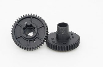
3D Printing Black Photosensitive Resin

3D Printing Large Sculptures
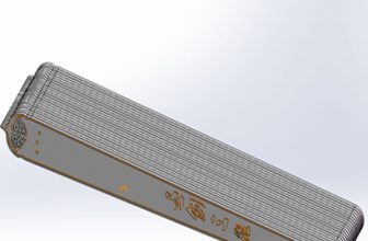
The Peach Blossom Fan Of 3D Printing
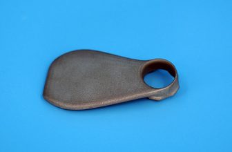
3D Printing Fine Electronic Mold Parts
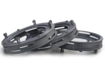
3D Printing Model Of PA12 Material
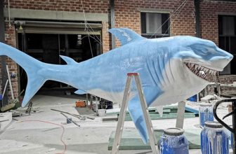
Big Shark Case 3D Printing Production
PTJ offers online 3D printing services for china rapid prototyping and production of non-metal and metal 3D printed parts at affordable prices.
- * Supports drawing uploads in file formats “.pdf”, “.jpg”, and “.png”.
- * Supports file uploading and loading of 3D (3D) CAD data “.igs” and “.step”.
- * Supports file uploading of two-dimensional (2D) CAD data “.dxf” and “.dwg”.
- PC
- ST-130
- PA 2200
- CoCrMo
- PA 3200 GF
- ABS M30
- Ceramic
- POM-like
- ULTEMTM 9085
- Paraffin Material
- Polyphenylsulfone
- Polyetheretherketone
- Soft Rubber Material
- Aluminum Filled Nylon
- High Ultra-Fine Plastic
- Mold Steel MS1
- NickelAlloy IN718
- Titanium Alloy Ti64
- White Photosensitive Resin
- Black Photosensitive Resin
- Transparent Photosensitive Resin
- Full Color Photosensitive Resin
- Micro-nano Material
- High Ultra-Fine Plastic
- Full-Color Gypsum Composite Material
GET IN TOUCH OR GET A QUOTE
PTJ 3D Printing
Mobile WhatsApp WeChat:
+86 8288 6112
+86 152 1709 1354
Email: [email protected]
Address: Dongguan City, Guangdong Province, China.
