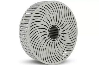
Get a closer look at GE’s 3D printing of an integrated turbine cover with cooling channels
The 3D printing integrated structure is a representative design for additive manufacturing (DfAM) structure. When designing with the thinking of additive manufacturing, it is necessary to break through the thinking limitations brought by casting, die-casting, and machining in the past. This process is full of challenges.
With the application of structural integration in the field of new energy, the application points that can outperform the market in the next 5 years will be realized from “points” and “surfaces”, from a corner to “lift”, “jump” and shape The overall situation of change, and 3D printing has a natural cost advantage in realizing structural integration. With the application points that can outperform the market in the next 5 years, it will realize the development of “point” and “surface” applications. New ascent route. Interestingly, GE continues to develop 3D printing to achieve the advantages of structural integration. Recently, GE has passed the patent of 3D printed integrated turbine cover (with internal cooling).
Limitations of film cooling and impingement cooling
The gas turbine system generates power by flowing fluid (eg, hot gas) through the turbine components of the gas turbine system. The intake air is mixed with fuel to form combustion products, so that multiple rotating blades rotate, and power is generated by the rotor or shaft of the turbine component.
During operation, the turbine shroud may be exposed to the high temperature working fluid flowing through the turbine components. Over time, the turbine shroud may experience undesirable thermal expansion. Thermal expansion of the turbine shroud can cause damage to the shroud. When the turbine shroud is damaged or no longer forms a satisfactory seal in the turbine components, the working fluid may leak from the flow path, which in turn reduces the turbine components and the overall turbine system. operation efficiency.
In order to minimize thermal expansion, it is often necessary to cool the turbine cover. Conventional processes used to cool turbine covers include film cooling and impingement cooling. Film cooling involves flowing cooling air over the surface of the turbine shroud during the operation of the turbine components; impingement cooling uses holes or holes formed through the turbine shroud to provide cooling air to various parts of the turbine shroud during operation.
These cooling processes will cause problems during the operation of the turbine components. According to the understanding of 3D Science Valley, the cooling air used in film cooling can be mixed with the working fluid flowing through the fluid flow path and may cause turbulence in the turbine components. In addition, the turbine shroud often has a patterned surface that can improve the seal with the rotor during operation. However, the patterned surface is generally not conducive to the film cooling process used to cool the shield.
Impingement cooling also has its drawbacks. In order to form impingement holes or holes through various parts of the turbine shroud, the turbine shroud must be formed from multiple parts and then installed into the turbine component. Integrate cooling as they are assembled to form a turbine
GE has developed a new type of integrated turbine shroud for turbine systems. Multiple turbine shrouds are directly coupled to the turbine housing and positioned radially between the turbine housing and multiple turbine blades. A hot gas channel (HGP) sealing groove is formed on the two opposite turbine shroud slopes; between the HGP surface of the sealing part and the HGP sealing groove, a plurality of slope exhausts are formed on each of the two opposite slopes A plurality of inclined exhaust holes are in fluid communication with the exhaust passage.
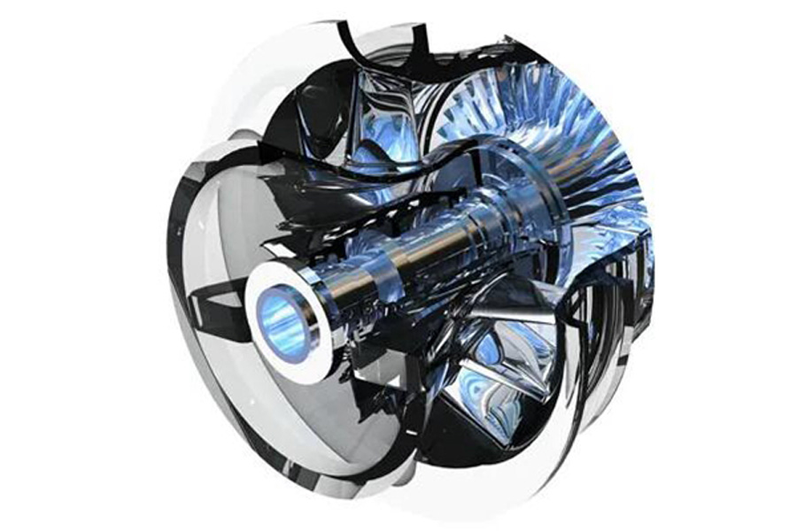
A side view of a part of a turbine of a gas turbine system, including turbine blades, stator blades, rotor, turbine casing, and turbine shroud.
The one-piece body of the turbine shroud may be formed in a single 3D printing-additive manufacturing process, and the turbine shroud may also include a pressurizing chamber and cooling channels formed therein.
Additive manufacturing is particularly suitable for manufacturing turbine shrouds with a one-piece body. Additive manufacturing can create complex geometries without the use of any type of mold, and there is almost no waste. In particular, the one-piece body turbine shroud realized by additive manufacturing may include a portion of the hot gas path that can be directly coupled to the turbine housing.
Structural integration is opening a new era created by 3D printing! According to GE’s patent US10781721B2, GE has developed an integrated turbine center frame through 3D printing-additive manufacturing. The additively manufactured turbine center frame includes an annular shell, an annular hub, and an annular fairing extending between the shell and the hub. The fairing includes an inner wall and an outer wall, and a plurality of ligaments extend from the outer wall of the fairing to the outer shell to connect the fairing to the outer shell. The additively manufactured turbine center frame also includes a plurality of struts extending from the hub to the casing and a pair of bosses defined on the outer surface of the casing.