Table of Contents
Since the 1970s, carbon fiber has been used as a relatively cheap alternative metal, such as titanium material, due to its high strength-to-weight ratio and rigidity. Therefore, finding a method for 3D printing with carbon fiber and other reinforcing materials has become the goal of many start-ups and mature manufacturers in the field of additive manufacturing.
We will study this wonderful material in a short series of articles that traces the roots and life cycle of carbon fiber, how to use carbon fiber in manufacturing and how to weave it into 3D printing. To understand how and why carbon fiber reinforced materials are used in 3D printing, it is helpful to understand how carbon fiber reinforced materials are used in traditional manufacturing and how carbon fiber parts are manufactured.
Global carbon fiber technology development
Whether you know it or not, carbon fiber has entered your world. Although it is mainly used in aerospace, it is also increasingly entering the fields of automotive, civil engineering, electronics and sporting goods. One of the main goals in the aerospace industry is to reduce the weight of aircraft, thereby reducing the expensive fuel required to push large aircraft into the sky. The Boeing 787 Dreamliner became the first aircraft made of 50% composite materials (mainly carbon fiber), but was recently replaced by the Airbus A350 XWB, which has 52% carbon fiber reinforced polymer (CFRP) parts.
In the automotive industry, due to the price of carbon fiber, CFRP components are more likely to appear in special vehicles, such as racing cars and super sports cars. BMW has used its expertise in materials for mass-produced i3 and i8 electric vehicles, and its chassis is made of a large number of CFRP parts. By using carbon fiber, car companies can reduce the weight of their vehicles, allowing the battery to further drive the car. However, the updated iNext will reduce CFRP projects, partly because of increased battery capacity and increased demand for electric vehicles, which will reduce the cost competitiveness of carbon fiber.
If you are an avid tennis player or cyclist, you may have invested in a carbon fiber racket or bicycle frame. Also, you may drive over a bridge that has been transformed with carbon fiber reinforced concrete.
Carbon fiber manufacturing method
Carbon fiber was invented in the second half of the 19th century and used as the filament in a light bulb. It was not until 1958 that Union Carbide began to manufacture carbon fibers for manufacturing, and researchers all over the world were pursuing this goal at the same time. Today, about 90% of carbon fibers are made by heating a petroleum-derived polymer called polyacrylonitrile (PAN). Due to its ubiquity, we will continue to focus on the production of PAN-based carbon fiber. Before heating the PAN to 300°C, it is wound into filament yarns and then stabilized to anticipate the next step: carbonization. In the carbonization process, the precursor material is drawn into a long strand and heated to 2000°C in an inert (oxygen-free) chamber. Without oxygen, the material will not burn, but will remove all carbon except carbon atoms. The result is a thin filamentous carbon layer that is only 5 to 10 microns thick. The carbon fiber is then immersed in gas (air, carbon dioxide or ozone) or liquid (sodium hypochlorite or nitric acid) so that it can be more easily bonded with other materials.
Carbon fiber can be wound into reels, so-called “tows”, and then used in this form. However, it is more common to weave it into a thin plate. These sheets are then combined with a polymer resin matrix to make CFRP parts. The way this happens depends largely on the type of component to be manufactured. The carbon fiber board can be put into a mold, and then filled with resin in the mold and heated or exposed to air until it hardens. Alternatively, the mold can be lined with reinforced fiber cloth and then placed in a vacuum bag filled with resin. These processes are usually labor-intensive, which is why metal molds are used to stamp the matrix material and carbon fiber material together when mass production is required. The use of prepreg materials can speed up these processes. Prepregs use reinforcing fibers that have been saturated with a polymer matrix and are easy to deploy.
For large-scale operations such as airplanes, more advanced and expensive methods of laying carbon fiber have been developed. Automatic tape laying can be on a prepreg tape with a width of 3 to 12 inches, and then use a large mechanical gantry system to wind it onto a part for heating and compression. Although its throughput rate is not the same, but the automatic fiber placement (AFP) technology and carbon fiber tow perform similar operations, which can achieve higher accuracy and geometric complexity.
Anisotropy
It is worth mentioning that carbon fiber exhibits anisotropic (direction-dependent) characteristics. Consider a fiber-reinforced material, such as a wooden board, which is most helpful: the stiffest along the texture. Therefore, when manufacturing reinforced fabrics, carbon fibers are often woven in a crisscross pattern. This feature will come into play as we understand the various methods of introducing carbon fiber into 3D printing (for example, the strength of chopped carbon fiber compared to continuous carbon fiber).
Carbon fiber in 3D printing
Many of the above technologies and applications can be found in the entire world of carbon fiber 3D printing. Some emerging methods for fiber-reinforced 3D printing rely heavily on prepregs, while other methods use tows. In the second part, we will specialize in various technologies currently used for carbon fiber 3D printing.
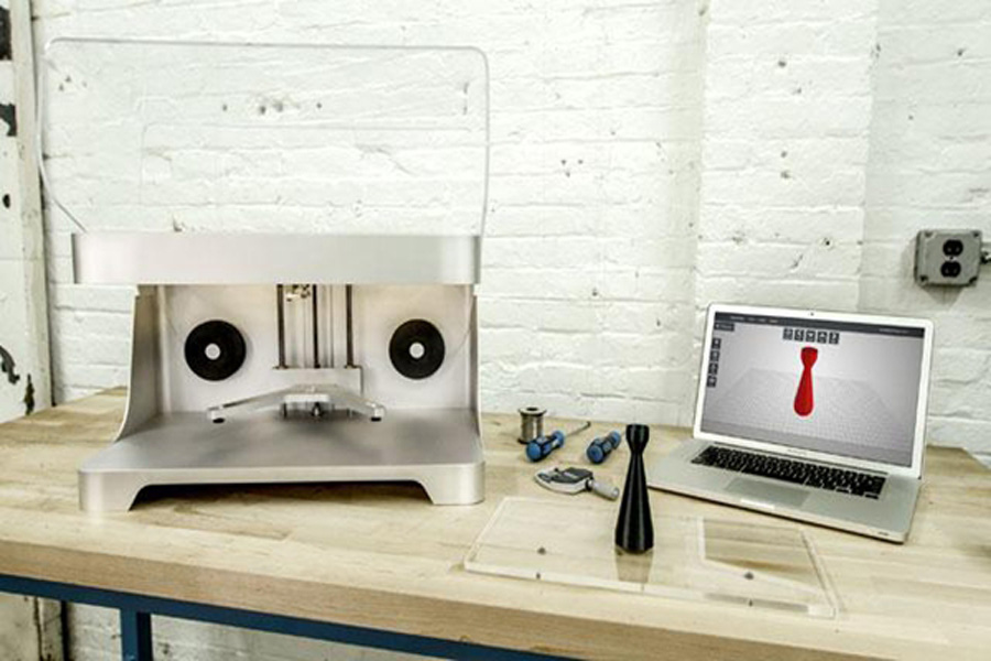
The most widely used form of carbon fiber in 3D printing is chopped carbon fiber filaments. There are a variety of chopped carbon fiber blends to choose from, and 3DXTECH offers some of the most diverse types, including high-temperature thermoplastics as the matrix material. For example, you can buy PA, PEKK, PEEK and PEI (ULTEM) filaments filled with chopped carbon fiber.
In chopped carbon fiber filaments, the carbon fiber segments are mixed with thermoplastic pellets and then extruded into filaments suitable for extrusion 3D printing. Because carbon fiber is broken, not connected, it can only provide the stiffness of carbon fiber where the small fragments are located.
However, the introduction of carbon fiber into the thermoplastic filament can improve its strength and stiffness, but it may also have a negative effect. A team of researchers found that in addition to the required strength, PEEK-carbon fiber composites have higher porosity and poorer adhesion between printed layers. Another group found that resin chopped carbon fibers used in stereolithography had similar results, including increased brittleness.
This does not mean that chopped carbon fiber filament (or resin) has no value in 3D printing, especially because it is much cheaper than the technology we will discuss. However, we will see in the third part of this series how to improve these materials with some very clever thinking.
In 2014, Markforged introduced continuous filament manufacturing (CFF) to the world. In CFF, carbon fibers are pre-impregnated with thermoplastic nylon, which is deposited from a special extruder. It is then used to reinforce plastic parts, including the company’s own chopped carbon fiber filament Onyx.
Recently, a Russian company called Anisoprint has commercialized its continuous carbon fiber printing version as composite fiber coextrusion (CFC). Unlike CFF, its prepreg has one input and one output, and CFC uses two inputs and one output. One input is dedicated to reinforcing fibers, and the other input is used to feed thermoplastics. Dry fibers are fed into the system and immersed in liquid thermosetting resin. During the printing process, the thermosetting material is cured with traditional thermoplastic filaments and extruded together. Then, the thermosetting matrix that has penetrated into the reinforcing fibers is bonded to the filaments.
How CFC works
As a result, not only has there been little opportunity to introduce bubbles or voids in the prepreg, but it has also opened up a variety of thermoplastics that can be used by CFC (to date, PETG, ABS, PC, PLA, and PA).
The deposition rate can also be controlled in CFC to generate interesting structures and characteristics that cannot be achieved by traditional composite manufacturing, such as lattice shapes. In the traditional case, when one carbon tow is passed through another carbon tow, the thickness of the area will be doubled. With CFC, the extruded thermoplastic can be reduced while still depositing carbon fibers, thereby reducing the amount of plastic in this area.
In turn, this increases the so-called “fiber volume ratio”, the amount of fiber reinforcement present relative to the total volume of the composite material. A higher fiber volume ratio usually means improved mechanical properties. Therefore, since these carbon fibers are crisscrossed with a 3D printed lattice structure, the fiber volume ratio and strength are increased.
In the aerospace industry, engineers seek a fiber volume ratio of up to about 60%. However, when using other carbon fiber 3D printing technologies, the ratio is close to 30% to 40%. Without the lattice structure, CFC can reach about 45%. At the point where the carbon fibers overlap, the ratio is doubled, which is stronger than traditional composite materials.
In woven carbon fiber, multiple layers of unidirectional fibers are staggered to simulate isotropy, and ultimately provide omnidirectional strength at the expense of excess material. However, when using CFC, the material and strength can be increased only when necessary. Therefore, Anisoprint emphasizes that the anisotropy of carbon fiber is an advantage, not a weakness, and the project technology is named “Anisoprint”. Since Markforged and Anisoprint entered the market, the third challenger has appeared in the form of its own continuous carbon fiber printing. Before Formnext 2019, Desktop Metal introduced a technology called Micro Automated Fiber Replacement (μAFP). μAFP relies on two print heads: one places thermoplastic filaments, then swaps one tool changer to the other, and lowers the prepreg tape, similar to the automatic fiber placement technique briefly mentioned in Part 1.
First, the carbon fiber thermoplastic tape is heated to a temperature higher than the melting temperature of the plastic. Then, the roller presses the tape on the printed part. The combination of heat, pressure, and cooled printed parts allows the tape to melt the parts. Desktop Metal is releasing the technology through Fiber HT and Fiber LT 3D printers. The annual subscription price of LT is US$3,495, and it can print PA6-carbon fiber or PA6-glass fiber tape. HT ($5,495 per year) can not only use these tapes for printing, but also PEEK or PEKK combined with carbon fiber or glass fiber. HT also has two print heads, while LT has only one. In addition, Fiber HT also has the ability to use advanced settings in its software to manage fiber direction, can achieve porosity less than 1%, and can print with fiber volume ratios as high as 60%.
Large format and experimental carbon fiber 3D printing
Also on Formnext, Anisoprint introduced its production-scale CFC system, the Anisoprint ProM IS500. The system has a build volume of 600 mm x 420 mm x 300 mm. The system has a heated build chamber that can print PEEK and PEI, and can perform automated calibration and other production quality functions. With four interchangeable print heads, in addition to carbon fiber, it will also be able to combine different composite materials. The system will also be equipped with software for optimizing the printing of lattice structures. Anisoprint’s goal is to deliver its first ProM IS 500 system by the end of 2020. Although this is the first production-grade carbon fiber 3D printer of a Russian company, it may face fierce competition. There are many other companies that are working on carbon fiber 3D printing in their own unique ways. Since they are very different from the types discussed here, we will explore them in the next chapter of this series.
So far, we have introduced some key aspects of carbon fiber manufacturing, and the comparison of continuous carbon fiber with the chopped cut in early carbon fiber 3D printing mode. However, there are some emerging methods of 3D printing composite materials.
Composite additive manufacturing CBAM
After years of research, Illinois-based Impossible Objects has begun to commercialize its composite-based additive manufacturing (CBAM) process. In CBAM, the bonding material is first deposited on the reinforcing material sheet and then filled with thermoplastic powder, which only sticks to the bonding material. The powder is then blown out or evacuated. All that is left is the plastic matrix on the reinforcing fiber sheet. The same process continues layer by layer, and these sheets are stacked one after another. Finally, the stack is compressed and moved into an oven where the plastic matrix is melted together. After removing the object from the oven, use a chemical bath or sand plastic to remove the excess matrix material, leaving the final object.
The reinforcement materials range from carbon fiber and glass fiber to polyester, polyvinyl alcohol, PLA and even silk and cotton. Since the powder does not melt when initially deposited, the variety of matrix materials may be much wider than other 3D printing processes. Currently, the company has demonstrated the use of PEEK and Nylon 12, but is developing an elastomer for CBAM and other materials.
Objects printed using this technology can be 10 times stronger than parts made by Fused Deposition Modeling (FDM). The CBAM-2 3D printer can print on 12-inch x 12-inch paper, but the company’s founder Robert Swartz envisions that it can print parts as large as the hood of a car, and the speed can reach 100 meters per minute.
The geometry is limited by the required post-processing. Sandblasting will limit the complexity of the shape because it is difficult to reach the internal geometry. The chemical process makes the structure more complicated because the excess material is dissolved away. Although CBAM cannot make parts as strong as those made with traditional composite materials, it can make more complex parts faster than parts made with traditional technology. It also saves labor.
CBAM-2 is still a new product on the market. It was launched in May 2019 and is expected to be delivered in the third quarter of this year. However, no news about the initial shipment has been released yet. We do know that Impossible Objects’ flagship Model One system is indeed introduced to customers including Ford Motor Company and Jabil.
CEAD
The two former co-founders of Leapfrog 3D printers Lucas Janssen and Maarten Logtenberg left the desktop 3D printing business to develop large continuous carbon fiber 3D printers. The two established a company called CEADgroup, dedicated to creating large-scale, fast, reliable, and capable of producing solid parts. The result is continuous fiber additive manufacturing (CFAM), which, according to the company, can 3D print parts with dimensions of 4m x 2m x 1.5m at a rate of 15 kg/h. For example, in the injection molding industry by using industrial extruders and hoppers to process plastic particles, fast deposition speeds can be achieved. The substrate materials that can be printed so far include PET, PP, ABS and PEEK. Reinforcing materials are limited to carbon fiber and glass fiber, but the company hopes to expand to include optical glass, copper and steel fiber.
CEAD claims that CFAM can increase the strength of parts by up to six times by adding continuous fiber reinforcements, but the exact nature of feeding the reinforcements into prints has not been disclosed.
Arevo
Arevo, a Silicon Valley startup (partly supported by CIA’s In-Q-Tel), has developed a laser-based carbon fiber printing method. The process deposits pre-impregnated continuous carbon fiber filaments and simultaneously heats it with a laser, then compresses it onto the build surface with a roller. The deposition head is mounted on a multi-axis robotic arm and can be 3D printed in any direction most suitable for part design, thereby making up for or taking advantage of the anisotropy of carbon fiber. The software developed by Arevo can also optimize the design through the use of simulation. So far, Arevo has demonstrated the capabilities of its Directed Energy Deposition (DED) technology by manufacturing bicycle frames for multiple companies. Recently, it cooperated with Japan’s AGC to provide manufacturing as a service.
Another start-up company developing a 3D printing method for continuous carbon fiber is Continuous Composites in Idaho. Its continuous fiber 3D printing (CF3D) method sends a roll of dry carbon fiber into the print head installed in a seven-axis industrial robot. Inside the print head, the fiber is impregnated with a fast-curing photopolymer resin, then drawn out through the end effector, and immediately cured with a powerful energy source. Like Arevo’s robots, the seven-axis arm can orient the fibers in any way necessary to overcome or take advantage of the anisotropic properties of the material. Unlike Arevo, dry carbon fiber is used as a starting material, it is possible to improve the physical properties of the final part and open up a variety of available matrix materials. Interestingly, the curing of the resin also allows the CF3D process to print in the air.
The reinforcing materials being developed so far include: carbon fiber, glass fiber, Kevlar fiber, continuous copper wire, continuous optical fiber, nickel-chromium alloy wire and silicon carbide. Although fiber optics can be used to embed sensors in parts, copper wires can be embedded in electronics, and nickel-chromium alloys can generate heat for deicing applications. Continuous Composites is developing automatic tool replacement to exchange print heads containing different fibers and resins. The resin is being developed with potential customers, but so far, the company has developed a weather-resistant, UV-resistant plastic with a high glass transition temperature, and the material meets the FAA’s smoke, fire, and toxicity requirements.
strengthen
As we mentioned earlier, chopped carbon fiber is weaker than continuous carbon fiber. However, Fortify is a start-up company, with its digital composite manufacturing (DCM) technology, the segmented characteristics of the material has unique advantages. DCM is a new type of digital light processing (DLP) technology in which a projector is used to cure the photopolymer resin. In the case of DCM, the liquid will be filled with reinforcing additives, such as chopped carbon fibers, which will be aligned using a magnetic field during the printing process.
In turn, additives can be oriented when necessary to achieve the best physical properties of the entire part. DCM can produce parts with the same geometric complexity as standard DLP parts, but with fewer supporting structures and larger overhangs. So far, the company is still in the early stages of manufacturing parts for potential customers, but the reinforcement materials developed so far include carbon fiber, glass fiber and high-temperature ceramic additives. In particular, the company believes its technology is valuable for injection molding printing tools.
In addition to the startups mentioned in this series, there are more well-known companies and research institutions that use carbon fiber to do interesting things. In 2016, EnvisionTEC (the inventor of DLP) demonstrated a large 3D printer, which is said to be capable of 3D printing composite materials. However, we haven’t heard of anything since, so some people want to know if it really exists. Stratasys also worked with Siemens to develop a carbon fiber 3D printing method, but there is no update in this regard.
Oak Ridge National Laboratory (ORNL) has also been researching this material and has assisted Cincinnati to provide large-area additive manufacturing technology. The process is characterized by the rapid deposition of short fiber-filled plastic to a shape close to the final shape, and is responsible for 3D printing Shelby Cobra replicas and Local Motors vehicles. Thermwood has created another version of the process, and Ingersoll is reported to be working with ORNL on a larger system in 2016, but no update has been provided so far.