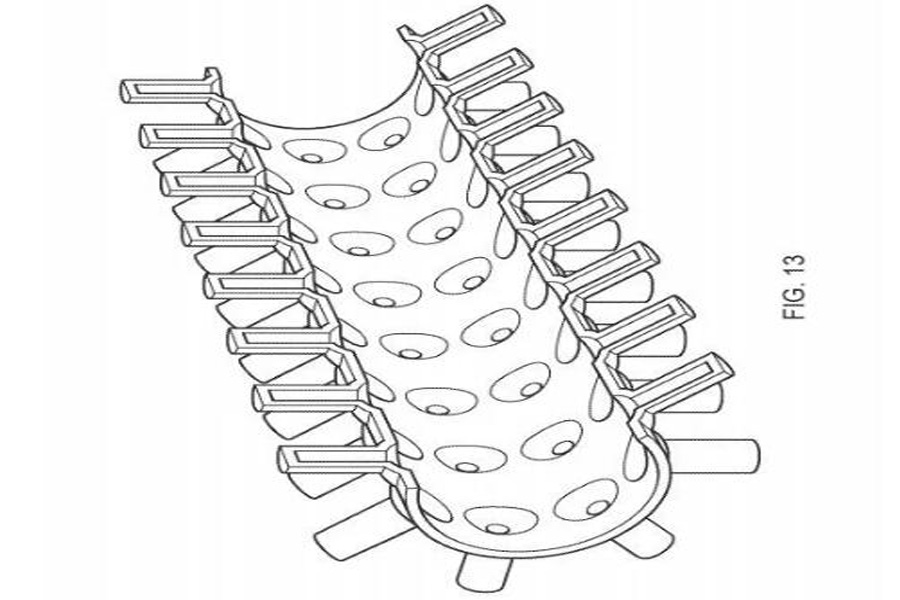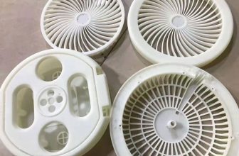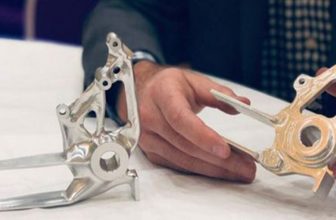
Heat Exchanger-The heat exchanger extracts heat from the turbine exhaust of the turbine engine and uses this heat to preheat the air leaving the engine compressor before flowing through the combustor. The heat exchanger of the micro-turbine engine, like many other heat exchangers, the heat exchanger can be manufactured in many different ways, but the typical heat exchanger manufactured in the traditional way is a brazed or welded plate-fin type. The fins can be traditional straight fins or corrugated fins, pin fins or mesh fins.
Heat exchangers are very suitable for manufacturing through additive manufacturing, but an attractive or generative design is often not enough by itself. It is understood that this also includes a mastery of the basic principles of heat transfer/fluid mechanics, a deep understanding and combination of thermal fluid simulation and AM-additive manufacturing processes, which are necessary to obtain convincing and competitive results .
Complex design 3D manufacturing
Micro-turbines have a wide range of potential applications in the fields of automobiles, national defense, aerospace, and clean energy. However, this potential has not been realized to a large extent, on the one hand, due to the high cost of recuperator heat exchangers, and the size and weight of the heat exchangers will bring certain adverse effects.
Another problem of existing recuperators manufactured by traditional methods, especially high-temperature recuperators, is the lack of robustness, which is caused by thermal fatigue and stress at sharp corners and rectangular joints, and brazing And most other connection methods inevitably produce this kind of fatigue and stress.
Another problem with traditional heat exchangers and other heat exchangers is that in microturbines, the source of the heat exchange fluid (at the outlet of the compressor and the inlet of the combustion chamber) may be a certain distance apart. This means that a large number of manifolds may be required, which greatly increases the volume, weight, and cost, and also leads to thermodynamic losses. Due to the large volume of the heat exchanger and its manifolds, their location may not be optimal, resulting in a further reduction in efficiency.
The heat pipe can be manufactured in various ways. The simplest is that the heat pipe can be in the form of a tube in which a core in the form of a mesh sleeve is inserted. The composite wick can contain multiple elements: for example, a sintered material with small pores can provide driving capillary force, while a channel with a larger opening can provide greater fluid flow and less fluid friction. With the development of additive manufacturing methods, especially the development of selective laser melting metal 3D printing technology (SLM), pin-fin heat exchangers have now been directly constructed through 3D printing technology.
Lighter, more compact, and more efficient
Sustainable Engine Systems Co., Ltd. has developed a heat exchanger in which part or all of the heat exchanger is replaced by one or more heat pipes. This significantly increases the thermal conductivity of the different components of the heat exchanger and allows reduction in size, weight and cost.
The manufacture of this heat exchanger is achieved through additive manufacturing technology, especially selective laser melting metal 3D printing technology (SLM), and needle fins in the form of heat pipes replace the needles in conventional needle fin plate heat exchangers. Shaped fins. Current pin-fin heat exchangers are suitable for a variety of heat pipe categories, including loop heat pipes, capillary pump heat pipes, pulsating heat pipes, variable conductivity heat pipes, rotating heat pipes, and adsorption heat pipes.
Generally, the end of the hot evaporator part will be in thermal contact with the partition, and the other side of the partition will be in contact with the colder fluid. There is a risk that the performance of the evaporator may decrease. By using selective laser melting metal 3D printing technology (SLM), the end of the pin-fin heat pipe is gradually tapered to reduce the heat transfer contact with the partition while maintaining sufficient contact for bonding and strength purposes. This effect can be reduced minimize. In addition, in half of the finned heat pipes, the evaporator will be located above the condenser, which may cause the heat transfer performance to be worse than that achieved in the finned heat pipe where the evaporator is located below the condenser, due to the lack of gravity assistance to the capillary force . In these cases, the relative proportion and/or size of the two directions of the pin-fin heat pipe can be adjusted by the selective laser melting metal 3D printing technology (SLM) to compensate for the difference in the performance of the heat exchanger. Each pin-shaped fin is independent heat pipe.
The evaporator and condenser parts of the needle-fin heat pipe can be tapered. By these means, the size, weight and cost of the entire heat pipe can be reduced. This design also has the advantages of heat transfer and pressure drop. The tapering of the needle-fin heat pipe can bring greater fin efficiency, without the similar geometric shape change as the traditional needle-fin heat pipe, which leads to an increase in size and weight.
Smaller, lighter and cheaper
SLM is a convenient and cost-effective method for mass production of such pin-fin heat pipes. Subsequent processing includes through electrical discharge machining or other methods. In this regard, the machining company GF Machining Solutions and 3D Systems have created a new concept of factory automation, including additive manufacturing part design software, 3D printers, materials and automated material processing, electrical discharge machining (EDM) equipment, milling equipment and other advanced post-production Processing technology.
Selective area laser melting metal 3D printing technology (SLM) brings the convenience of structural integration. In the pin-fin heat pipe design version, the baffle and pin-fin heat pipe can be integrated into a single structure, thus eliminating any welding or The need for brazing.
The vapor flow from each needle-fin evaporator is opposite to the direction of the vapor entering the liquid, flows downward from the center of the needle-fin evaporator tube, enters the main heat pipe through the same hole, and gathers into a strip. The larger vapor stream passes through the main pipe and then flows along the adiabatic section to the condenser in the normal way. In the condenser, the liquid and vapor streams have similar distribution and accumulation, respectively.
Arranging a pin-fin evaporator with an appropriately varying length at the circular outlet of the microturbine has potential benefits including reducing the thermal stress problem inherent in the design of traditional high-temperature heat exchangers; reducing or even eliminating manifolds; reducing fluid friction; through more optimization The design improves the compactness of the system.
The SLM pin-fin heat exchanger also reduces or even eliminates the problem of powder removal inherent in the SLM structure. For very low pipes with a diameter of less than 1 mm and complex internal structures, in this case, it is difficult or impossible to ensure that all excess powder particles have been removed. If these powder particles are removed (for example, recuperator) Transporting to the compressor or turbine may damage the blades or turbine, which may cause serious consequences. For the SLM heat pipe, the space where the loose powder may remain is sealed inside the heat pipe and cannot reach any moving parts, which will not adversely affect the performance of the heat pipe. This type of design increases the main direct heat transfer surface area between the heating fluid and the cooling fluid and the heat pipe working fluid. In turn, the secondary surface area required on the outside of the heat pipe will be reduced, making the overall system smaller, lighter and cheaper.


