Open-cell honeycomb structures exist in nature in different forms. Today, polymers, metals and ceramic porous materials have played a role in industrial production. These structures have excellent performance at high temperatures, stability in harsh environments (acidic, alkaline, or oxidizing), and excellent thermomechanical properties (thermal shock resistance). Due to their porous nature, they have a fluid phase with higher surface area and permeability, so they are suitable for applications in catalysis, solar energy collection, heat storage, heat exchange, radiation burners and other fields.
Traditional ceramic honeycomb structure manufacturing methods include: uneven pore molding, direct foaming and duplication of polymer foam. And additive manufacturing-3D printing technology has become a new manufacturing process for ceramic foam materials. By combining CAD, simulation and additive manufacturing, it can meet the needs of end users in different industrial fields.
In the paper “Cellular ceramic architectures produced by hybrid additive manufacturing: a review on the evolution of their design”, researchers reviewed the design tools and design methods of honeycomb ceramic structures for additive manufacturing, and proposed some innovative tools. It also shows the industrial application cases of ceramic honeycomb structure realized by these design methods. In this issue, I will first share the first part-the design part of ceramic honeycomb structure, and the second part will share the application cases of 3D printing ceramic honeycomb structure in industrial fields such as burners, heat exchangers, and solar receivers.
Evolution of honeycomb ceramic design
Random foam design
Random foams are characterized by random and non-periodic structures. They exhibit scattered characteristics and it is difficult to determine their behavior. The 3D digital tool Matlab can be used to generate random foam composed of strut elements. The script uses a list of nodes and edges obtained by a method that includes an X-ray computed tomography (XCT) scan of the real foam (Figure 1(a)) and skeletonization of the generated output file.
The data set also contains the connections (edges) between nodes. Set the sample size as input, and the algorithm will randomly crop the skeletonized bubbles. The result is that the array of nodes and edges can be scaled to achieve a specific size of the hole. The array is then converted to a STEP file, which contains a set of spheres (centered in each node) and cylinders (with the edges as the main axis). The porosity of the foam can be defined by adjusting the diameter of the sphere and cylinder. Such STEP files can be imported into commercial CAD software for numerical simulation or foam additive manufacturing.
Although foams are widely used in engineering applications, they still have design limitations, such as inability to blend into containers, local defects that reduce component performance, and they cannot be replicated.
Structured lattice design
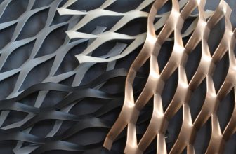
The unit cell with periodic boundaries can fill the space forming the lattice structure, and the lattice structure is generated by copying the unit cell in three directions.
There are several unit cell libraries in Matlab, namely: cube, rotating cube, hexagon, octagonal truss, tetradodecahedron and Weaire-Phelan polyhedron. The selected lattice is copied in space to form a data set containing nodes and connection positions. The lattice (usually in the form of a parallelepiped) can then be tailored to the desired shape.
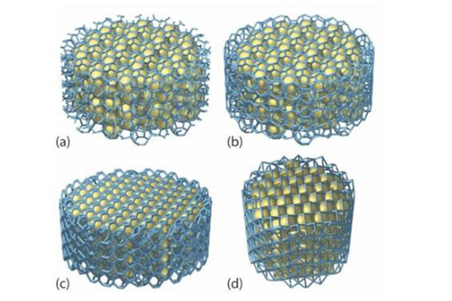
The disadvantage of this method and the previous method is the presence of unconnected struts at the boundary (Figure 2a). In many applications, this is a big problem when manufacturing, handling, and operating components. To avoid this, connect the pillar to the second tool. By finding the convex hull containing these points, each group of points belonging to the trimmed unit cell on the boundary (on the edge of the free strut) can be identified and connected to each other. Figure 2 (b-d) depicts the three lattice structures generated by this method.
l Grasshopper
Grasshopper is a visual programming language environment, mainly used to build generative algorithms, but its advanced uses include parametric modeling for structural engineering, parametric modeling for architecture and manufacturing, and lighting performance for eco-friendly buildings. Analysis and building energy consumption. As shown in Table 1, the algorithm contains several unit cell libraries composed of lines, and can also manage other types of unit cells.
When designing, select the required lattice and copy it in the space until the volume of the required size and shape is filled. Then convert the line array into a 3D triangle mesh created using Cocoon add-ons, and output an STL file that can be processed immediately for 3D printing. Compared with the previous algorithm, this algorithm has several advantages: short generation time, allowing real-time visualization of the final structure and real-time attribute calculation of surface area, volume, porosity, etc.
Unstructured lattice design
In many cases, in order to design a lattice with heterogeneity (such as variable cell size and orientation), it is best to arrange the structure of the unit cell to be disordered. Traditionally, hexahedral and tetrahedral mesh elements have been used to discretize the numerical domain in computer simulations. Extracting edges from unstructured grids can produce equivalent unstructured grids in the form of simple cubic or tetrahedrons. Extending this method, nodes and element connections can be extracted from unstructured hexahedral grids, and the required periodic unit pixels can be mapped to each grid cell. This method can use any unit cell with cubic symmetry. Figure 3 shows some examples of unit cells with cubic symmetry.
Matlab follows this idea by receiving a grid file as input and generating an unstructured lattice structure with a specific unit cell as output. The hexahedral mesh of the part can be used to map the scaled unit cell onto it. The diameter of each pillar can be adjusted individually, even for a single part, different unit cells can be used, so that an unstructured lattice with variable unit cell and variable pillar diameter can be generated.