For a long time, traditional modeling methods and manufacturing processes that cannot achieve complex geometric shapes have restricted breakthroughs in heat exchanger design and efficiency. However, high-performance and complex geometric structures for additive manufacturing and high-strength aluminum alloy 3D printing materials, It brings new possibilities for breakthroughs in heat exchanger design.
3D Science Valley once shared a design case of additively manufactured aircraft fuel oil heat exchanger (FCOC). In this issue, 3D Science Valley will continue to discuss this case with Gu You, but today’s focus is on the design process of this 3D printed aircraft fuel oil heat exchanger, as well as the advanced design and additive manufacturing reflected in this process. New possibilities to improve the performance of FCOC heat exchangers.
The design process consists of three steps: the original CAD design, the design in the nTOP platform, and the fluid dynamics simulation analysis (CFD) through ANSYS CFX.
Aircraft engines obtain powerful thrust by burning fuel, and generate a large amount of heat that needs to be dissipated during the combustion process. In modern airplanes, the fuel stays in the wings and becomes low-temperature fuel as a result. The fuel cooled in the wings of an aircraft may crystallize and block the system, but the cooled fuel also provides a way to regulate the temperature of the aircraft combustion chamber, mechanical and electrical systems. Through the fuel oil heat exchanger (FCOC) to transfer heat energy between the oil and fuel, it will be able to play the following roles:
Make the oil cool enough to lubricate and cool the system
- *Prevent fuel crystallization
- *Bring the fuel close to the ignition temperature
Unlock advanced aviation heat exchanger design and simulation
In the design project of FCOC’s new generation of high-performance heat exchangers, the requirement is to replace traditional shell-and-tube heat exchangers with additive manufacturing heat exchangers, and to study whether advanced design and additive manufacturing can be used to improve this heat exchanger Performance.
l Improve thermal performance in limited space
Designers need to optimize the design in a given limited space. An effective method is to use advanced geometric figures to mathematically control the geometric figures inside the design space. In the FCOC project, the designer uses the nTOP platform to define a volume for FCOC design iterations. The iteration method is to maximize the surface area while minimizing the wall thickness.
In this case study, a triple-period minimum surface (TPMS) was used, which has both a high strength-to-weight ratio and a very high surface-to-mass ratio. Gyroid is a type of TPMS that can be used to define the internal volume. By using a spiral structure in this heat exchanger, the surface area of the spiral structure is increased by 146% compared with a conventional shell-and-tube heat exchanger of the same size.
Gyroid = S in(x)Cos(y) + S in(y)Cos(z) + S in(z)Cos(x)
When this design is combined with additive manufacturing technology, it will be possible to realize parts with high strength and heat dissipation requirements that have not been possible in the past.
In order to achieve the minimum wall thickness, the designer chose the high-strength 7000 series aluminum alloy (7A77.60L) specially developed for additive manufacturing as the heat exchanger manufacturing material. As a result, the wall thickness of FCOC can be minimized while still meeting the requirements of aircraft The critical burst pressure structure requirements. The yield strength of 7A77.60L aluminum alloy is almost twice that of casting grade additive manufacturing aluminum alloy AlSi10Mg, and the wall thickness of the spiral structure made from this material can be reduced to half of the original design.
The surface area is increased by 146%, and the wall thickness is reduced by half, so that the total heat transfer of the FCOC in the same volume is increased by about 300% compared with the traditional design.
l Fluid mechanics simulation predicts the performance of additive manufacturing heat exchangers
ANSYS CFX is an advanced computational fluid dynamics solver used to evaluate the performance of FCOC. Throughout the design iteration phase, multiple CFD simulations were used to evaluate the design.
Based on the initial simulation results, the designer optimized the energy distribution method inside the spiral tube, thereby increasing the total heat transfer coefficient by 12%. From nTop platform to ICEM (for mesh refinement and conversion) and ANSYS CFX is a repeatable workflow that can help designers quickly design iterations.
l Design method
Next, let’s take a look at the specific design method of additive manufacturing FCOC heat exchanger.
Figure 4 outlines the process of converting geometry from the nTop platform to the selected CFD tool. The process is defined by the user isolating the fluid domain of the heat exchanger and generating the volume grid of these fluid domains in the nTop platform, and then importing these fluid volume grids into the CFD tool, applying appropriate boundary conditions, and performing fluid simulation.
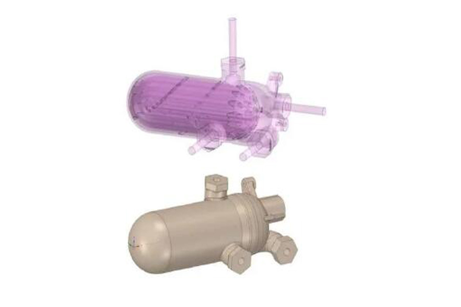
Before entering the nTop platform, FCOC’s initial design concept went through many design iterations on paper and computer-aided design (CAD). The main design considerations include: minimizing pressure drop, enhancing flow characteristics, introducing impact to improve heat transfer coefficient, and designing for additive manufacturing.
CAD entities and surfaces are used to define the volume of the heat exchanger. Use these objects and surfaces to design the filling volume of the TPMS structure. The tools in the CAD software Cero are used to generate the shell and dome structure of the heat exchanger.
l Design for additive manufacturing in the nTop platform
When the boundary representation is finalized in the CAD software Creo, the assembly will be saved as a single entity, and these entities will be imported into the nTop platform. After importing, in order to use the CAD geometry correctly in the nTop platform, it is necessary to convert the parts to nTop implicit entities.
Through the nTop platform, the perimeter, radius and height period, unit cell and wall thickness can be changed. Designers can customize the shape of the spiral structure to meet performance requirements, such as surface area and cross-sectional flow area. This geometric control also allows designers to adjust how fluid enters and exits to minimize the total pressure drop while optimizing the system-level performance of the heat exchanger. Figures 7-10 show how to adjust the unit cell size, perimeter count, and height period to achieve a smooth flow path throughout the heat exchanger.
At this point, the designer has imported and converted the CAD geometry into nTop implicit entities, and generated the fluid domain. The next step is to create baffles or flow dividers. This step is to prevent the mixing of the hot and cold fluids.
The main challenge in this step is to generate the volume for intersecting the fluid volume. This may require designers to convert additional CAD entities (faces, edges, vertices) and assign parameter control parameters so that the workflow is repeatable as the CAD geometry changes. Once the intersecting volume is generated, simply select the appropriate fluid to be blocked. Most of the intersecting volume is created by extracting CAD surfaces, then converting them to nTop implicit solids and thickening them. The other intersecting volumes use the original geometry block to generate new geometry. The main module used is the torus, which is then remapped to create an arched channel, resulting in a structure that is more friendly to additive manufacturing.
At this point, the baffle design process has been completed, and it is necessary to assemble the newly formed heat exchanger core to the heat exchanger assembly. In this process, the nTop platform can seamlessly create rounded corners between the periodic baffle structure and the “solid” geometry.
l Import ANSYS CFX
This session will describe the discrete nTop platform for CFD simulation. As previously described in Figure 4, the fluid domains and heat exchanger walls have been generated, and what is needed now is to generate a volume grid of these areas.
Both CFX and Fluent are good solvers, and design users can choose according to the type of physics to be solved. For example, for high Mach number/supersonic flow, Fluent is preferred, while for turbomachinery and other incompressible fluid simulations, CFX can be preferred. In order to set up and define any type of computational analysis, the user must apply boundary conditions to select surfaces. These include but are not limited to fluid inlet and outlet surfaces.
After defining the boundary surface and transforming the mesh, import each fluid domain into ANSYS CFX. The defined surface can be identified and can be easily assigned to its appropriate boundary conditions. When the outlet is 0 kPa, the inlet mass flow rates of fuel and oil are set to 0.45 kg/s and 0.3 kg/s, respectively.
Once the workflow from nTop platform to CFD is established, design users can continue to use the process throughout the design iteration. The grid output from the nTop platform can be recognized as a design update in ICEM, which can then be re-imported and the entire CFD workflow repeated.
Summarize
In the case of additive manufacturing aircraft fuel oil heat exchanger (FCOC) design and fluid dynamics simulation, the overall feasibility of performing CFD on the complex geometry generated in the nTop platform has been proved.
The nTop platform can create complex geometric figures (TPMS structure, fluid volume, smooth lattice-solid transition) while maintaining complete control over the geometric model, and then export the geometric figures to an external simulation platform for verification. While integrating with external CAE tools, the ability to perform such complex operations in a single tool is unprecedented, and can allow rapid design iterations on complex geometries.
ICEM CFD is a module of ANSYS, used for mesh refinement, transformation and generation, as a boundary selection tool.