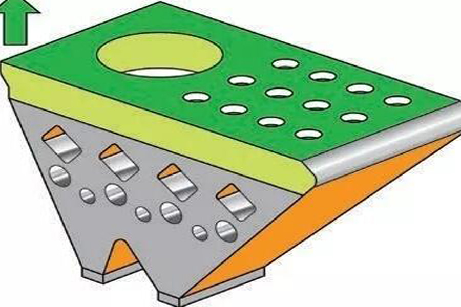
Powder bed laser melting (LPBF) is a versatile additive manufacturing process that can produce complex metal parts directly from CAD files without expensive molds and minimize material waste. The selection of the process parameters used to melt and solidify the metal powder is critical because the thermal reaction of the alloy affects its integrity and strength. The correct selection of parameters suitable for the processed materials and specific parts is the key to successful processing, especially in mass production applications.
Renishaw (Renishaw) Additive Manufacturing Application Director Marc Saunders explained how to calculate the ideal process parameters for metal additive manufacturing (AM) parts, discussed the consideration factors for the selection of powder bed laser melting process parameters, and how these factors define “operations” Window” and analyzed the sensitivity of the machining process to changes in the geometric shape of the part, which is why it is necessary to select specific parameters for specific applications when performing part 3D printing.
Melting characteristics and its influence on part density
LPBF overview
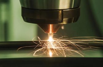
Powder bed laser melting is to focus the high-energy ytterbium-doped fiber laser beam into a small spot, so that it has enough energy intensity to completely melt the thin layer of metal powder. The laser is moved on the powder bed through a pair of scanning galvanometers, and the metal powder is melted under the action of the laser and solidified and connected with the lower layer and adjacent areas to form a molten pool. Protect the airflow through the processing tray, protect the hot metal from oxidation, and safely remove smoke and dust.
The width of the weld bead is larger than the laser spot (approximately 2 to 3 times the diameter of the spot), because the heat generated by the laser will be transferred to the surrounding powder particles and melt them into the moving molten pool. Multiple molten tracks are connected to each other and overlapped to form a solid metal layer corresponding to the layering of the parts. The melting track must be deep enough to partially remelt the underlying metal layer to form a completely dense solid structure. Powder bed laser melting 3D printing equipment builds parts layer by layer in this way.
Continuous wave and modulated laser melting
There are two main techniques for melting metal powders-continuous wave and modulated scanning. Continuous mode, as the name implies, refers to continuously transmitting laser energy to melt powder. The method used in this technology is to guide the laser beam to scan the surface of the powder bed back and forth to solidify the metal powder. Because the scan lines overlap, each successive scan will partially remelt the previous scan line and solidify into welding consumables.
In the modulation mode, the laser works slightly differently. A series of exposures are produced by repeatedly turning the laser on and off, with a short interval (10-20 microseconds) between the two exposures. The area exposed each time will partially overlap with the area exposed last time, thereby forming an approximate scan line. These scan lines efficiently sweep through the powder bed to solidify the powdered metal.
Basic introduction of process parameters
The way the laser energy is delivered to the powder bed depends on the process parameters. These parameters determine the energy intensity and scanning speed. The key parameters are:
- Laser power: the total energy emitted by the laser per unit time.
- Spot size: the diameter of the focused laser beam-it can be fixed or edited, depending on the focusing system of the machine.
- Scanning speed: The speed at which the light spot moves on the powder bed along the scanning vector—determined by the point distance and exposure time of the modulated laser system.
- Scan line distance: The distance between adjacent scan vectors to remelt the previous weld pass to a certain extent to ensure that the area to be melted is completely covered.
- Layer thickness: the depth of each new powder layer to be melted.
The above parameters can be adjusted individually, so parameter selection is a multivariate selection.
Determine the “operation window”
The primary consideration for selecting parameters is to make fully dense parts with uniform quality. Part density is a key indicator of melt quality—if porosity is present, the required strength, ductility, and fatigue/creep resistance cannot be achieved. But how to choose the right combination among countless parameters?
Turn the complexity into simplicity, and get twice the result with half the effort. For each given workpiece, the chemical properties and particle size distribution of the powder are determined. The layer thickness can also be determined according to the fineness of the part and the surface finish requirements. After the laser spot size is determined (many equipment does not allow to change the spot size during processing), you only need to select the laser power, scanning speed and scanning line distance.
If the scanning speed is too fast and the laser power is too low, some areas of the part may not be completely melted, resulting in voids due to “insufficient melting”. Conversely, if too much power is applied at the selected speed, it may overheat the molten pool and penetrate too deeply into the energy, leading to a “deep hole” effect.
Between these two extremes is an “operating window”, within which a good part density can be obtained. In this window, the laser energy is sufficient to completely melt the powder and the metal layer below it, without penetrating too deeply.
It can be seen from Figure 2 that increasing the laser power and scanning speed at the same time can improve the processing efficiency, which is feasible to a certain extent. However, there is a limit to power and speed. Once this limit is exceeded, the molten pool will become unstable and a “spheroidization” effect will occur. When the laser power increases, spatter may also increase.
Processing in the “operating window”
The central “operating window” on the P-V graph is the correct combination of speed and power to produce a stable molten pool of the best size, as shown in Figure 3. Under this combination condition, the laser energy is effectively absorbed by the powder to form a molten pool of sufficient depth, which is firmly fused with the underlying metal layer, while avoiding excessive remelting.
In this processing zone, the laser recoil pressure creates a shallow cavity. The laser moves and heats the front of the cavity, creating a plume of metal vapor sprayed perpendicular to the surface (that is, upward and backward). Since there is no internal reflection in the shallow cavity, excessive melting does not occur. Heat energy is conducted into the molten pool, and due to the high temperature gradient and surface tension in the molten pool, a certain degree of turbulence appears in the molten pool. This flow can cause certain substances to be ejected in the form of welding spatter.
The moving vapor plume creates an environment similar to a weather system around the molten pool. It can roll up powder from around the weld bead, pull the powder into the laser beam through the Bernoulli effect, and then spray it out. Part of the powder is melted when passing through the laser, and the remaining powder is blown away by the induced air current like “wind” near the laser beam.
Insufficient melting
If the power applied at a given speed is too small, the molten pool will become smaller. This means that the curing speed becomes faster, the turbulence becomes smaller, and the spatter decreases. The vapor plume will become weaker and the amount of powder that will be rolled up will also be reduced.
The disadvantage of this is that the lower laser energy may not penetrate to a sufficient depth, and thus cannot completely melt the powder layer and the top layer of the metal solid below. As shown in Figure 4, this leaves unmelted powder underneath, leading to excessive porosity and the risk of delamination.
Deep hole formation
If too much power is applied at a given speed, the laser will excessively penetrate into the metal layer below the powder layer, resulting in the formation of deep holes. In this case, a deep cavity will be formed on the surface, and the metal vapor injection on the deep cavity will be more vertical. The internal reflection of laser energy inside the cavity will conduct more heat to deeper locations in the material, resulting in a deeper molten pool and longer duration. An increase in energy input will result in greater turbulence in the molten pool and increased spatter, while the “weather system” will become more intense, and more powder will be rolled up.
If the deep hole is unstable (affected by power, scanning speed, and molten pool dynamics), the molten pool will collapse on the cavity, causing inert pores to form at the bottom. When the molten pool solidifies, these pores may not close, thus creating subsurface pores in the metal solid. The underlying metal layer will also undergo a greater degree of remelting, which in turn affects the microstructure of the solidified material.
When using an infrared camera to measure the nickel-based alloy molten pool from above, they observed that the length of the molten pool is approximately constant when the same laser power is applied at different scanning speeds. However, as the speed decreases, the molten pool becomes wider and the area becomes larger. In this study, when a laser power of 200 W was applied at a speed ranging from 200 mm/sec to 800 mm/sec, the length of the molten pool was approximately 0.6 mm. The wider (and thus deeper) molten pool formed at a slower scanning speed has more heat energy and therefore longer curing time — in the most extreme case in Figure 7 below, it takes as long as 3 ms.
“Spherization”
When the scanning speed is too fast, the molten pool will become unstable. A high surface tension gradient will cause voids to be formed behind the laser beam. These voids will expand with the movement of the laser, causing the molten pool to decompose and eventually solidify into multiple disconnected spheres.
Powder bed laser melting (LPBF) is a versatile additive manufacturing process that can produce complex metal parts directly from CAD files without expensive molds and minimize material waste. The selection of the process parameters used to melt and solidify the metal powder is critical because the thermal reaction of the alloy affects its integrity and strength. The correct selection of parameters suitable for the processed materials and specific parts is the key to successful processing, especially in mass production applications.
Renishaw (Renishaw) Additive Manufacturing Application Director Marc Saunders explained how to calculate the ideal process parameters for metal additive manufacturing (AM) parts, discussed the consideration factors for the selection of powder bed laser melting process parameters, and how these factors define “operations” Window” and analyzed the sensitivity of the machining process to changes in the geometric shape of the part, which is why it is necessary to select specific parameters for specific applications when performing part 3D printing.
Optimal laser process
Curing and microstructure
For the formation of performance characteristics of metal parts, the most critical thing is the curing process. The curing process determines the microstructure, which in turn forms the material properties.
Many alloys are complex and may exist in multiple phases at different temperatures and compositions, so they will not solidify all at once, and generally do not solidify uniformly in the weld bead. The cooling rate is very fast in the place where heat is easy to dissipate, and most of the heat will be conducted from the molten pool to the surrounding solid metal. A relatively small amount of heat will be dissipated into nearby unmelted powder, or radiated into the processing chamber through radiation.
As the molten metal cools down, the temperature of the outer region of the molten pool also drops below the liquidus temperature, at which time one or more phases of the alloy will begin to solidify. The outer edge of the molten pool will form honeycomb dendrites and grow toward the center. The remaining liquid phase stays between these primary dendrites and will not solidify until it reaches its lower melting point. The opposing honeycomb dendrite growth front forms a separate grain boundary, and the remaining liquid phase will also gather in the grain boundary.
The cooling process will apply strain to these honeycomb and grain boundary regions, and through the “hot tear” or solidification cracking process in some materials, voids that should not exist may be generated. If the curing temperatures of the different phases differ greatly, the worst will happen.
As you can see, the size, duration and cooling rate of the molten pool are important because these factors determine the thermal response of the material. The longer molten pool has a slower cooling rate and will produce a rougher microstructure with larger crystal grains and thicker dendrites. In contrast, a smaller molten pool cools faster and can form a finer microstructure.
A deeper molten pool will also cause a greater degree of remelting of the solidified metal, which will affect its microstructure. Higher laser power results in the formation of longer columnar vertical grains, each of which spans multiple layers. Since the deeper molten pool has a larger contact area with the metal solid below, more heat is conducted downwards, resulting in the formation of more grains in the vertical direction. This will increase the difference in mechanical properties between the vertical and parallel machining directions.
Optimal laser process
Therefore, the Renishaw team decided to calculate an ideal combination of speed and power to form a molten pool with the best depth, width and duration. In other words, the parts are processed with optimal energy. Finding the right combination can reduce porosity and form a microstructure that meets the requirements of material properties and productivity.
One way is to calculate the “energy density”, which is the energy applied to a unit volume of material. When the energy density is constant, the laser power is inversely proportional to the scanning speed. Therefore, in the P-V coordinate system, the energy density contour line radiates from the origin, and the density is related to the gradient of the contour line.
For the selected material and layer thickness, there is an optimal energy density, which can achieve the highest processing efficiency and the most accurate microstructure. When selecting process parameters, we hope to stay away from the boundary as far as possible within the capabilities of the laser and focusing optical components of the additive manufacturing equipment to avoid risking entering the spheroidization zone. In order to achieve optimal material properties and productivity. In the above figure, “X” is the best processing point.
Scan line distance
A key factor is missing from the above analysis: the scan line distance. The above schematic diagram assumes that the scanning line distance is fixed, so the energy density is only determined by the laser power and scanning speed.
In fact, the scan line distance can vary independently of power and speed, and it also affects energy density. Therefore, the same energy density can be maintained along multiple P-V contour lines by changing the scan line distance. Therefore, the same energy can be applied to the processing layer in many different ways.
All three contour lines shown by the orange arrows in the figure below have the same energy density. For example, if a higher power/speed ratio is used (that is, we choose a steeper contour line closer to the deep hole formation area), the energy density can be kept constant by increasing the scan line spacing. This is feasible because if a more penetrating laser beam is used to form a wider and deeper molten pool, the spacing between the scan lines can be increased while ensuring that all scan lines are fused with each other.
However, due to the above-mentioned reasons, doing so will result in poor material properties. The closer to the deep hole formation area, the lower the process safety factor, so these parameters may not be suitable for certain geometries. Therefore, a scan line distance that can reach the central P-V contour line must be selected, and the contour line should be far away from insufficient melting and deep hole formation.
The parameter combination in the blue area in the above figure should be able to achieve a qualified process result, but “X” is the most ideal processing point. Since most of the energy from the laser beam is absorbed in the laser spot at the center of the melting track, generally speaking, the scanning line distance closest to the spot size (or about half of the melting track width) has the best processing efficiency.
Layer thickness
In the case discussed above, the layer thickness is fixed. What happens if the layer thickness is changed? If the requirements for surface finish are not high, can the layer thickness be increased to improve processing efficiency?
To a certain extent, the answer is yes. Obviously, the thicker the powder layer requires the deeper penetration of laser energy to ensure complete fusion with the underlying metal layer. In order to obtain the optimal energy input to completely melt the material, as the layer thickness increases, the energy input of each layer must be increased accordingly. As a result, the energy density contour line becomes steeper.
The increase in layer thickness will enlarge the “insufficient melting” section in the above figure, thereby narrowing the gap between it and the section where the deep hole is formed. The deep hole formation interval itself may not vary greatly with the layer thickness, because this effect is controlled by the intensity and speed of the laser spot and the way the laser spot interacts with the material.
As a result, the operating window gradually becomes smaller, and finally at a certain layer thickness, while maintaining the stability of the molten pool and fully fusing with the underlying metal layer, it cannot penetrate to a sufficient depth.
The feasible layer thickness that can provide a reasonable operating window varies from material to material, but generally speaking, when the laser power reaches 500 W and the spot diameter is 70 to 100 microns, the feasible layer thickness ranges from 30 to 90 microns.
For thicker powder layers, the spot size can be increased accordingly to reduce the spot intensity under higher laser power. However, this change can result in a loss of fidelity, an increase in weld pool size and spatter, and may also affect the microstructure and material properties.
Why is a safety factor required?
The reason for the need for a wider operating window is that the thermal conditions of all areas on the workpiece are not always constant. With each additional layer, the heat will be conducted down to the processed metal layer below. The heat dissipation depends on the local geometry and material properties of the part.
If there is a good thermal connection with the underlying substrate, the heat will be effectively dissipated. In contrast, if the geometry of the part contains thin walls, or if the solid part is processed directly above the thinner part, the heat will not be conducted smoothly downwards, resulting in more heat remaining near the top layer of the part. This effect is most obvious in materials with relatively low thermal conductivity (such as Ti6Al4V).
Under this condition, the substrate and powder have been preheated, so less energy input is required to produce the same melting effect. The effect of this preheating on the melting process is to expand the deep hole formation interval, resulting in the formation of deep hole pores at a lower power. The new optimal energy density contour line is lower than the original one, and the operating window is narrower. See Figure 15b.
One possible remedy is to use simulation techniques to identify areas where parts may overheat and reduce the laser energy input in these areas to counteract this preheating effect.
Combining this with the layer thickness factors mentioned above, the conclusion is that it is very difficult to process thin-walled parts with a thick powder layer.
Nominal and specific parameter sets
The focus of the above is to calculate the ideal physical process parameters of each material, so as to improve the processing efficiency of metal parts as much as possible. However, an effective parameter set requires more than one setting, because different areas of the part have different melting and cooling conditions. In order to make parts that meet the end use, special settings suitable for the various geometric shapes to be processed must be supplemented in the entity parameters.
Each part is composed of many solid parts and surfaces in different directions. The processing requirements of the solid part are high density, fast processing speed, and excellent material properties. However, the priority factors for the border section are different. The most important part of this part may be the surface finish, in order to avoid hiding surface defects, which in turn will cause damage to the parts during post-processing. The lower surface generally cools slowly because there is no solid substrate under it, so in this area, it is necessary to avoid deformation and scum as much as possible.
Very different parameters are usually used in these areas. Therefore, even the nominal parameter set contains a variety of settings and scanning strategies for different areas of the part. To ensure optimal quality in all areas of the part, more application-specific parameters need to be developed.
Summarize
The selection of process parameters is critical to the success of the additive manufacturing process, because it determines how the material will melt and solidify to form the parts we need. Since each alloy powder absorbs laser energy, transfers heat, flows and solidifies in different ways, the process parameters must be selected according to the specific characteristics of the alloy to be melted.
A wide operating window must be determined within the capabilities of the additive manufacturing equipment, and the optimal processing point must be found in the middle of the window, and the safety margin at this point should be able to adapt to various local melting conditions. Even so, some geometric shapes may still need to modify parameters to adapt to changes in remaining heat. The boundary and lower surface area may also require different process parameters and scanning strategies to meet the surface finish requirements.